


WENZHOU PROM TRADING CO.,LTD.
Contact Person:Lucy Guo
Tel/Wechat/Watsapp:+86 15990723109
E-mail: promtrading@sina.com
Skype:lucysolac
Legal Add:Room 804, Block 15, Jinlongyuan, No.81, Nixiang South Road, Kunpeng Street, Wenzhou Maritime Economy Development Demonstration Zone, Wenzhou, Zhejiang, China
Factory Add:Binhai industrial zone, Longwan, Wenzhou, Zhejiang, China
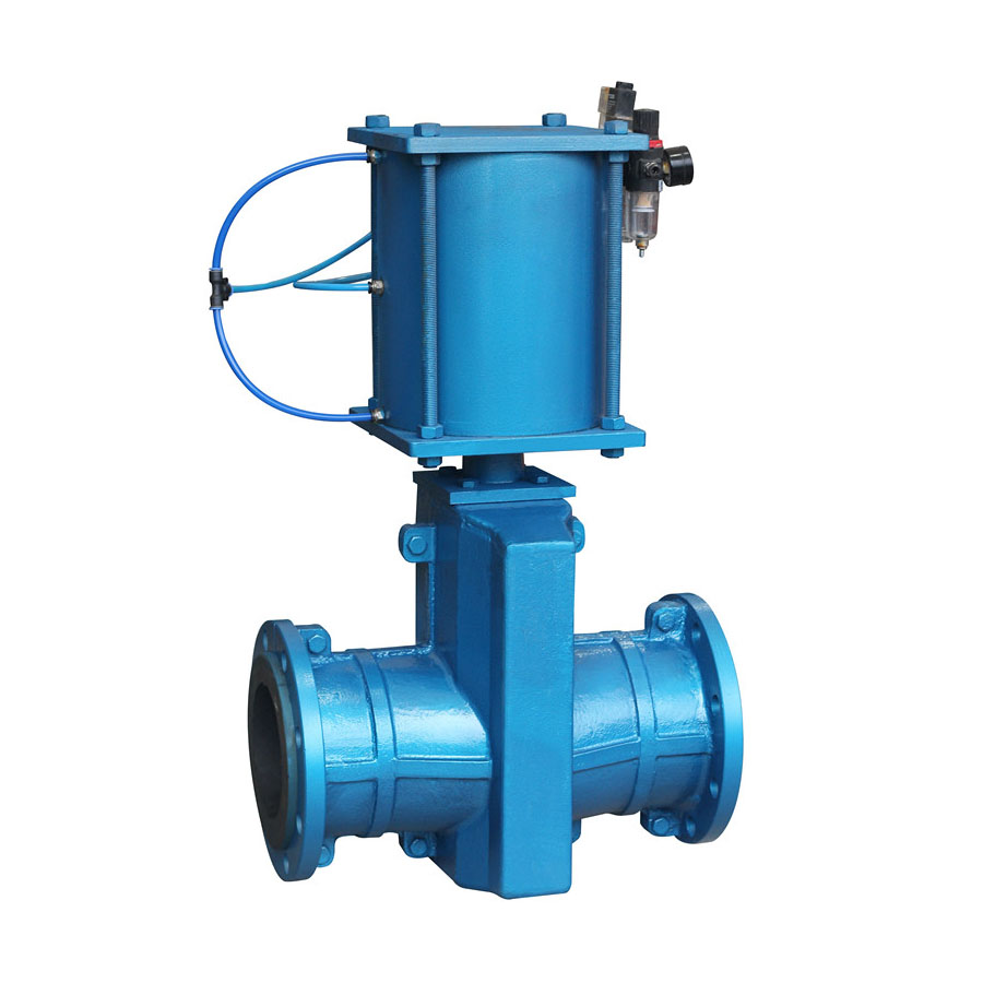
Cast iron pinch valve with pneumatic actuator
The hose gate valve is used in pipelines transporting streams with high viscosity or high content of abrasive particles. Classical shut-off valves do not work in such conditions, since the abrasive suspension can damage even the most resistant shut-off element. Therefore, in pipelines transporting heavily polluted streams, a special gate valve is used, the locking element of which simply clamps the elastic insert in the seat of the housing.
HOSE GATE VALVE — DESIGN FEATURES
Hose fittings, like any other locking element, consist of the following parts:
Enclosures
The locking unit
Management bodies
This scheme does not deviate from the classical layout of the shut-off valves. However, the specifics of the design of valves of this type are manifested in each node of this device. For example, the valve body is formed in the form of a tee, the horizontal of which is formed by the main ends, and the vertical by a fitting receiving an adjustment valve. However, there is no seat in the inner part of the valve body that accepts the locking element. The main ends of the fittings are designed in the form of threaded fittings (nozzles) or flanges.
The hose gate valve is flanged and the shut-off element of the hose fittings differs from similar parts of shut-off and control devices for pipelines in the most fundamental way. This unit is not designed as a rotating body, nor as a wedge – the locking element of the hose fittings is made in the form of an elastic, hollow cylinder (in fact, a piece of hose), which is simply squeezed by a wedge or piston.
The controls of the hose gate valve are designed according to the classical scheme: a threaded rod is inserted into the vertical end of the body, to the end of which a locking device is attached. The design features of the controls are manifested precisely in the form of a locking device that resembles a press. Moreover, the lock can consist of two halves – an upper and a lower one, which move towards each other, covering the elastic branch pipe. This is the principle by which the 33a17p hose gate valve operates, the lock of which consists of two parts.
Drawing of Cast iron pinch valve with pneumatic actuator

Materials of Main Parts
| No | Part Name | Material |
| 1 | Body | Cast Iron |
| 2 | Sleeve | NR |
| 3 | Spare part | CS |
| 4 | Stem | Q235A |
| 5 | Pneumatic actuator | Component |
Main Size & Weight
| PN, MPa | Working pressure, MPa | DN,mm | L | L1 | фD | фК | n-фd |
| 1,0 | 0,6 | 25 | 145 | 124 | 115 | 85 | 4-ф14 |
| 32 | 160 | 145 | 135 | 100 | 4-ф18 | ||
| 40 | 180 | 157 | 145 | 110 | 4-ф18 | ||
| 50 | 210 | 160 | 160 | 125 | 4-ф18 | ||
| 65 | 250 | 199 | 180 | 145 | 4-ф18 | ||
| 80 | 302 | 222 | 195 | 160 | 4-ф18 | ||
| 100 | 350 | 250 | 215 | 180 | 8-ф18 | ||
| 125 | 432 | 318 | 245 | 210 | 8-ф18 | ||
| 150 | 498 | 350 | 280 | 240 | 8-ф23 | ||
| 0,4 | 200 | 650 | 446 | 335 | 295 | 8-ф23 | |
| 250 | 797 | 516 | 390 | 350 | 12-ф23 | ||
| 300 | 930 | 562 | 440 | 400 | 12-ф23 | ||
| 350 | 840 | 790 | 500 | 460 | 16-ф23 | ||
| 400 | 910 | 840 | 565 | 515 | 16-ф26 |
*The above dimensions are for reference only.


